
By Sunhorizon | August 20, 2026
Table of Contents
- What Is an Encoder?
- Incremental vs. Absolute Types
- Mechanical, Optical, or Magnetic Sensing
- Key Parameters for Selection
- Quick Selection by Application
- Common Selection Mistakes
- Conclusion
- Sources
What Is an Encoder?
Choosing the right encoder starts with one basic question: What does the control system need to measure?
An encoder converts shaft movement into electrical signals. A controller can then use these signals to detect rotation, speed, direction, or position. Rotary models are common in industrial controls, audio equipment, machine panels, and human-machine interfaces.
The selection process should match the application, not just the price. Engineers should check signal type, resolution, shaft size, voltage, mounting space, operating environment, and service life.
Incremental vs. Absolute Types
The first major choice is between incremental and absolute encoders.
| Feature | Incremental | Absolute |
|---|---|---|
| Position at power-on | Requires reference or homing | Available immediately |
| Main output | A/B/Z pulses | Absolute position code |
| Typical use | Speed, direction, panel adjustment | Position monitoring, motor positioning |
| Cost | Usually lower | Usually higher |
| Best for | Audio controls and general motion | Systems that cannot lose position |
An incremental encoder generates pulses as the shaft rotates. The controller counts these pulses to determine movement. A/B signals can also indicate rotation direction. Position information normally depends on a known reference point.
An absolute encoder reports its angular position directly. It does not need a homing cycle after power-up. This makes it useful when the machine must retain position information through a power interruption.
Practical rule: use incremental output when the system only needs relative movement. Choose absolute output when the actual position must remain known.
Mechanical, Optical, or Magnetic Sensing
The sensing method also affects cost, durability, signal quality, and application range.
Mechanical Contact
Mechanical contact encoders have a simple structure and low cost. They can also include an integrated push switch. This makes them popular for audio knobs, control panels, and user-interface applications.
However, contacts can wear over time. Signal bouncing can also occur. The controller may need software debounce.
Optical
Optical encoders can provide high resolution and long service life. They suit high-precision motion systems and industrial equipment.
Their main limits are sensitivity to dust and vibration and a higher cost.
Magnetic
Magnetic encoders offer good resistance to dust and vibration. They can also provide long service life in compact equipment.
They may offer lower resolution than some optical solutions and can be affected by magnetic interference. They fit industrial equipment and harsh environments well.
Key Parameters for Selection
Resolution and PPR
PPR means pulses per revolution. It indicates how many pulses the device produces during one shaft revolution.
For common audio knobs, the source guide recommends 12–24 PPR. For fine adjustment, 32–48 PPR may be more suitable. Motor speed detection can require much higher values, such as 100–2000 PPR.
Higher resolution is not always better. OMRON recommends selecting resolution according to the precision required by the machine and checking the maximum response frequency against shaft speed.
A/B Phase
A standard incremental design uses two channels, A and B, with about a 90° phase difference. The controller uses their timing to determine rotation direction.
If direction is not required, some applications can use only one channel. For normal user-interface controls, however, A/B output provides better control flexibility.
Push Switch
A push switch adds a second function to the knob. The user can rotate the shaft to change a value and press it to confirm a selection.
This feature works well for menu controls, audio equipment, and front panels. If the application only needs speed measurement, a push switch may add unnecessary cost.
Shaft and Detent
Mechanical compatibility matters. A common solid shaft size is 6 mm, with round and D-cut options. Always confirm the shaft profile before ordering.
Detents provide a click at each step. They suit human-machine interfaces and audio panels. A smooth shaft without detents may work better for speed measurement.
Do not confuse PPR with detent count. A product can have 24 PPR but only 12 detents. Both specifications should be checked.
Electrical and Environmental Conditions
Check the controller voltage before selecting a part. The source guide lists 3.3 V and 5 V for consumer mechanical models, while industrial optical and magnetic models may use 5 V or 24 V. Mechanical contact outputs work at low current and should connect to MCU I/O rather than drive loads directly.
The environment also matters. Consumer-grade operating ranges in the guide are around -20°C to 70°C, while industrial-grade models can reach -40°C to 85°C. Dust, moisture, oil, and vibration should all influence the final choice.
Quick Selection by Application
A simple application-based approach can reduce selection time.
| Application | Recommended Type | Key Parameters |
| Audio volume/menu knob | Incremental mechanical | 24 PPR, 24 detents, push switch |
| Fine parameter adjustment | Incremental mechanical | 32 PPR, detent, push switch |
| Motor speed measurement | Incremental magnetic | High PPR, no detent |
| Motor angle positioning | Absolute magnetic | Absolute position output |
| Dusty industrial equipment | Magnetic | Environmental protection, suitable output |
| Long cable industrial wiring | Optical/magnetic | Differential or line-driver output |
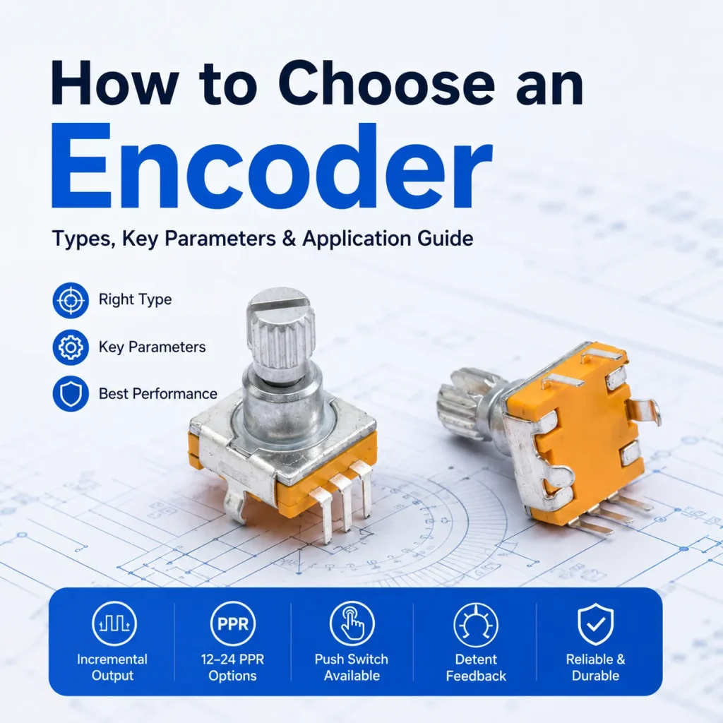
For an audio panel, the source material recommends an incremental mechanical model with 24 PPR, 24 detents, a push switch, a 6 mm shaft, 5 V supply, and A/B output.
For industrial systems, OMRON also recommends checking shaft loading, maximum speed, protection level, dimensions, and output circuit type. Long-distance transmission may benefit from a line-driver output.
Common Selection Mistakes
Several mistakes appear repeatedly in product selection.
First, choosing by PPR alone. Resolution must match the control system and shaft speed.
Second, ignoring detent count. PPR and click positions are different specifications.
Third, checking only the shaft diameter. The shaft length and D-cut or round profile can affect knob compatibility.
Fourth, overlooking the output circuit. The controller must support the selected signal format and voltage.
Fifth, selecting an optical or magnetic model when a simple mechanical design is enough. Extra performance can increase cost without improving the user experience.
Finally, confusing an encoder with a potentiometer. A potentiometer provides an analog resistance or voltage change. An encoder produces digital pulse or coded position information.
Conclusion
The best encoder is not necessarily the highest-resolution model. It is the model that matches the application.
Start with the required function. Decide whether the system needs relative or absolute position. Then select the sensing method, resolution, A/B output, push switch, shaft design, electrical interface, and environmental rating.
For audio panels and simple user controls, a 24 PPR incremental mechanical model with detents and a push switch is a practical starting point. For motor control and harsh environments, magnetic solutions may offer better durability. For position-critical machines, absolute technology can remove the need for a homing cycle.
A clear specification checklist can reduce compatibility problems, control errors, and unnecessary cost.