
September 22, 2026
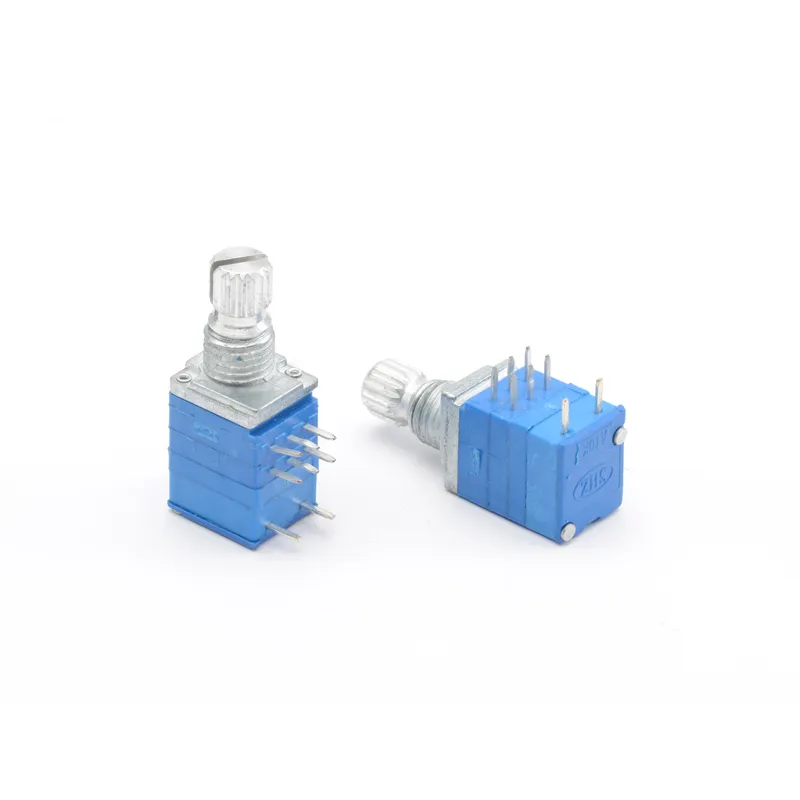
A switched potentiometer combines two functions in one component: variable resistance and electrical switching.
Instead of installing a separate potentiometer and switch, engineers can use one integrated control. This can simplify the panel layout and reduce the number of components required.
Switched controls are commonly used in audio equipment, lighting controls, appliances, automotive electronics, and other products where users need both adjustment and ON/OFF or function selection.
Table of Contents
- What Is a Switched Potentiometer?
- How Does a Switched Potentiometer Work?
- Common Types of Switched Potentiometers
- Switched vs Standard Potentiometer
- Key Parameters to Check
- Applications
- How to Choose a Switched Potentiometer
- OEM Customization
- Conclusion
1. What Is a Switched Potentiometer?
A switched potentiometer, also called a potentiometer with switch or switched rotary control, integrates a resistive control section with an electrical switch.
The potentiometer section changes resistance as the shaft rotates. The integrated switch operates at a defined mechanical position.
For example, an audio control may turn counterclockwise to reduce volume and then continue slightly further to operate the ON/OFF switch.
The switch has its own terminals, so it can operate separately from the resistive track.
2. How Does a Switched Potentiometer Work?
A standard potentiometer normally has three main terminals:
- Input
- Wiper
- Output or reference
The resistance changes according to the shaft position.
A switched version adds additional terminals for the internal switch.
Typical operation:
Rotate → Adjust resistance → Reach switching position → Switch changes state
Depending on the design, the switch can operate:
- At the end of shaft rotation
- At the beginning of shaft rotation
- Through push/pull shaft movement
- Through push-on/push-off movement
The exact switching action depends on the component design, so engineers should check the product datasheet before PCB or wiring design.
3. Common Types of Switched Potentiometers
Rotary Potentiometer with End-of-Travel Switch
This is a common configuration.
The shaft rotates normally for resistance adjustment. When it reaches a specified position, the internal switch changes state.
This design is useful when one knob needs to control both adjustment and power or function switching.
Push-Pull Potentiometer
A push-pull design uses axial shaft movement to operate the switch.
Instead of rotating the knob to activate the switch, the user pushes or pulls the shaft.
This allows one rotary control to provide an additional function without adding another panel switch.
Push-Switch Potentiometer
This design uses the knob as a push button. Pressing the shaft changes the switch state while rotation continues to control resistance.
The exact mechanism and electrical configuration depend on the product design.
4. Switched vs Standard Potentiometer
| Feature | Standard Potentiometer | Switched Potentiometer |
|---|---|---|
| Resistance adjustment | Yes | Yes |
| Integrated switch | No | Yes |
| Main control | Rotation / sliding | Rotation / sliding + switching |
| Terminal count | Usually fewer | Usually more |
| Panel space | Separate switch may be required | Two functions in one component |
| Wiring | Simpler | More complex |
| Typical use | Volume, tone, brightness | Volume + power/function control |
| Design consideration | Resistance parameters | Resistance + switch parameters |
The main advantage of a switched design is functional integration.
However, adding a switch does not automatically make a component suitable for every application. Switch rating, mechanical structure, mounting dimensions, and terminal arrangement must match the equipment.
5. Key Parameters to Check
Resistance Value
Common resistance values include 1KΩ, 10KΩ, 50KΩ, 100KΩ, 250KΩ, and 500KΩ, depending on the application.
The required value should be determined from the circuit design.
Resistance Taper
For audio applications, logarithmic or audio taper is commonly considered because it provides a more natural perceived change in volume.
Linear taper is often used when the electrical output should change more directly with shaft position.
Switch Configuration
Check the required switch configuration:
- SPST
- SPDT
- DPST
- DPDT
The correct configuration depends on what the switch needs to control.
Switch Electrical Rating
The potentiometer specifications and switch rating are separate parameters.
The switch has its own voltage and current limits. These must be checked against the actual circuit.
Shaft Type and Length
The shaft must match the knob and panel design.
Important dimensions include:
- Shaft diameter
- Shaft length
- D-shaped or round shaft
- Knurled shaft
- Threaded bushing
- Mounting height
Mounting Structure
PCB mounting and panel mounting have different requirements.
Before ordering, compare the component drawing with the PCB footprint and panel dimensions.
Mechanical Life
For equipment with frequent user adjustments, mechanical life should be considered according to the expected operating cycles.
6. Applications
A switched potentiometer can be useful when equipment requires two related user actions in a compact control area.
Audio Equipment
A common configuration is:
Turn → Volume adjustment
Turn to the end → Power switch
Audio equipment can also use dual-gang versions when two channels need simultaneous adjustment.
Lighting Equipment
A control can combine brightness adjustment with an ON/OFF function.
The exact circuit depends on the lighting system and the electrical rating of the switch.
Home Appliances
Compact panel controls can use an integrated rotary control when both adjustment and switching are required.
Automotive Electronics
Space can be limited in vehicle control panels. An integrated component can reduce the number of separate mechanical controls.
Industrial Equipment
For control panels, engineers may consider integrated rotary controls when a machine needs both parameter adjustment and local enable or selection.
7. How to Choose a Switched Potentiometer
A practical selection process can be divided into six steps.
Step 1 — Define the resistance
Determine the required resistance value and tolerance.
Step 2 — Select the taper
Choose linear, logarithmic/audio, or another required characteristic.
Step 3 — Define the switching function
Determine whether you need SPST, SPDT, DPST, DPDT, or another configuration.
Step 4 — Check the switch rating
Confirm that the switch can handle the required voltage and current.
Step 5 — Match the mechanical dimensions
Check shaft length, shaft diameter, bushing, mounting method, PCB footprint, and overall height.
Step 6 — Confirm operating requirements
Consider rotational angle, torque, operating cycles, temperature, sealing, and environmental conditions.
This process helps prevent a common purchasing problem: finding a component with the correct resistance but an incompatible switch or mechanical structure.
8. OEM Customization
For mass production, a standard component may not always match the customer’s PCB or mechanical design.
OEM projects may require customization of:
- Resistance value
- Resistance taper
- Shaft length
- Shaft shape
- Bushing
- Mounting method
- Terminal structure
- Switch configuration
- Torque
- Rotational angle
- Packaging
For replacement projects, it is especially important to compare the original component’s dimensions and terminal count rather than selecting a replacement based only on resistance value.
Additional terminals may indicate a second resistive section or an integrated switch, so the original wiring should be checked before replacement.
9. Conclusion
A switched potentiometer is designed for applications where one control needs to provide both variable adjustment and switching.
Compared with using a separate potentiometer and switch, an integrated design can simplify the control panel and reduce component count. However, selection requires more than checking resistance.
For an engineering or purchasing project, confirm:
Resistance + taper + switch type + switch rating + shaft + mounting + terminal layout + mechanical requirements.
For OEM production, providing the original drawing, PCB footprint, or sample can make component matching more accurate.
Related Resources
Small Rotary Potentiometers: 9mm & 11mm Guide
Rotary Potentiometer Technical Parameters & Selection Guide
Potentiometer Replacement Guide
Sunhorizon Potentiometer & Encoder Manufacturer