
November 4, 2026
Table of Contents
- Introduction
- How Does a Potentiometer Work?
- How Does a Hall Effect Sensor Work?
- Potentiometer vs Hall Effect Sensor: Key Differences
- Advantages and Limitations of Each Technology
- Common Applications in Modern Electronics
- How to Choose the Right Position Sensor
- Conclusion
- Sources
Introduction
Position control plays an important role in modern electronic equipment. From audio control panels to industrial machines and automotive systems, many devices need accurate and stable position signals.
Two common technologies are traditional resistive controls and Hall effect sensors. Both can measure rotary or linear movement, but they use different working principles.
A traditional potentiometer uses physical contact between a wiper and a resistive track. A Hall effect sensor detects changes in a magnetic field without direct electrical contact.
So, which technology is better?
The answer depends on the application, operating environment, service life, cost, and required signal output. Understanding these differences helps engineers select the right component for their designs.
How Does a Potentiometer Work?
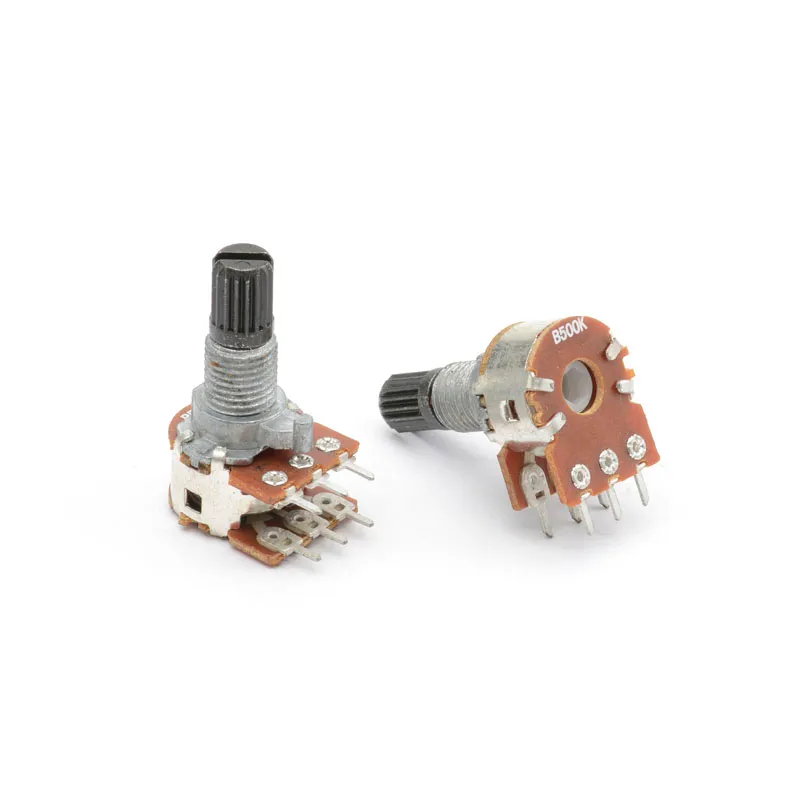
A potentiometer is a variable resistor with three main terminals. It contains a resistive element and a moving contact called a wiper.
When a user turns the shaft or moves a slider, the wiper changes its position along the resistive track. This changes the resistance between the terminals and adjusts the output voltage in a typical voltage-divider circuit.
Rotary and slide designs support different mechanical structures and installation needs.
Common types include:
- Carbon-film rotary models for audio volume control.
- Slide models for professional mixing equipment.
- Dual-gang designs for stereo audio circuits.
- Sealed models for applications that need extra protection from dust.
A carbon-track control offers a simple and direct way to adjust signals. It also provides a familiar mechanical interface for users.
However, the moving contact creates friction. Over time, wear, dust, and poor contact conditions may affect electrical performance.
For many electronic products, this technology remains a practical choice because of its simple circuit design, compact structure, and cost advantages.
How Does a Hall Effect Sensor Work?
A Hall effect sensor detects a magnetic field and converts it into an electrical signal.
The basic principle comes from the Hall effect. When electric current passes through a semiconductor and a magnetic field acts on it, a voltage develops across the material.
In a rotary position system, a magnet usually moves with the rotating shaft. The sensor detects changes in the magnetic field and calculates the shaft position.
Unlike a mechanical variable resistor, this design does not need a sliding electrical contact.
Key features include:
- Non-contact position detection.
- No resistive track or sliding wiper.
- Reduced electrical contact wear.
- Compatibility with analog or digital signal processing.
- Potential for long operating life in suitable conditions.
However, the system needs a suitable magnetic design and electronic circuitry. Magnet alignment, air gap, temperature, and external magnetic interference can affect its performance.
Engineers should consider these factors during product development.
Potentiometer vs Hall Effect Sensor: Key Differences
Both technologies can provide position information, but their structures and electrical characteristics differ.
The following table summarizes the main differences.
| Comparison | Resistive Pot | Hall Effect Sensor |
|---|---|---|
| Working principle | Physical contact | Magnetic field detection |
| Contact method | Mechanical wiper | Non-contact |
| Main structure | Resistive track and wiper | Hall IC and magnet |
| Electrical output | Variable resistance or voltage | Analog or digital signal |
| Mechanical wear | Possible | No sliding electrical contact |
| Circuit design | Relatively simple | Requires electronic circuitry |
| Power requirement | Depends on circuit design | Requires a power supply |
| Magnetic sensitivity | Generally low | Requires magnetic field control |
| Cost | Often economical | Depends on sensor and system design |
| Typical use | Manual adjustment and control | Position and motion sensing |
Neither option wins in every category.
A traditional adjustable resistor may offer a simpler and more economical solution for manual control. A magnetic sensor may suit systems that need frequent movement without mechanical electrical contact.
The correct choice depends on the actual design requirements rather than technology trends alone.
Advantages and Limitations of Each Technology
Advantages of Traditional Resistive Controls
One major advantage is circuit simplicity.
A rotary resistor can connect directly to a suitable analog circuit without a complex magnetic sensing system. Engineers can select resistance values, taper, shaft dimensions, and mounting styles according to their designs.
Other advantages include:
- Simple electrical connections.
- Compact mechanical structures.
- Wide resistance options.
- Direct manual adjustment.
- Competitive manufacturing costs.
These features make traditional designs useful in audio equipment, home appliances, control panels, and many consumer electronics products.
Their main limitation is mechanical contact. Repeated movement can gradually wear the resistive surface and wiper.
Advantages of Hall Effect Technology
The biggest advantage is non-contact operation.
Since the sensing element does not slide along a resistive track, the system avoids this type of mechanical electrical wear.
It can work well in applications with frequent movement and long operating cycles.
However, designers must consider magnet placement, calibration, power consumption, electronic noise, and environmental conditions.
A non-contact design does not automatically guarantee better accuracy. The complete sensor system determines the final result.
Common Applications in Modern Electronics
Different industries have different position control requirements.
Audio Equipment
Rotary controls remain common in amplifiers, speakers, and mixing consoles. Users need smooth and direct adjustment of volume, tone, and other settings.
A suitable carbon-film rotary design can provide a practical solution for these applications.
Automotive Electronics
Automotive systems may use both technologies.
Traditional mechanical controls can support certain manual adjustment functions. Magnetic sensors can provide position feedback in systems that need contact-free detection.
The choice depends on temperature range, vibration, service life, safety requirements, and circuit design.
Industrial Automation
Industrial equipment often needs stable position feedback.
Hall effect devices can suit systems with frequent movement. Mechanical variable resistors can also work well in control panels and adjustment mechanisms where simple analog output is sufficient.
Home Appliances
Appliances use rotary controls for temperature, speed, brightness, and operating modes.
A compact rotary model can offer an economical solution when the design needs direct manual adjustment.
For more demanding sensing applications, engineers may consider magnetic or optical alternatives.
How to Choose the Right Position Sensor
Before selecting a component, engineers should define the main operating requirements.
1. Identify the control function
Is the component used for manual adjustment or continuous position feedback? This is often the first question to answer.
2. Check the required signal
Determine whether the circuit needs variable resistance, analog voltage, or a digital signal.
3. Evaluate operating life
Consider movement frequency, mechanical load, vibration, and expected service cycles.
4. Review installation space
Check shaft length, body dimensions, mounting method, terminal layout, and PCB compatibility.
5. Consider environmental conditions
Temperature, humidity, dust, and magnetic interference may affect the final design.
6. Compare the complete system cost
Do not compare component prices alone. Include circuit changes, additional electronics, assembly, testing, and maintenance requirements.
For OEM projects, early sample testing can help confirm mechanical fit and electrical performance before mass production.
Conclusion
Traditional resistive controls and Hall effect sensors both have important roles in modern electronics.
A mechanical design offers simple connections, direct adjustment, and flexible customization. A magnetic sensing system provides non-contact operation and avoids sliding electrical contact wear.
Neither technology is universally better. Engineers should select components according to signal requirements, operating conditions, expected service life, and total system cost.
For projects that require compact rotary controls, stable resistance, or customized mechanical structures, choosing an experienced component manufacturer is also important.
Sunhorizon provides rotary and slide designs, encoders, and rotary switches for electronic equipment manufacturers. Resistance values, shaft dimensions, terminal structures, and other specifications can be discussed according to project requirements.
Visit Sunhorizon to explore available components and OEM solutions.
Authoritative References
- Texas Instruments – What Is a Hall-Effect Sensor?
- International Society of Automation – A Guide to Selecting Non-Contact Sensors
- ZF – Position and Speed Sensor Types
- SAE International – A Hall Effect Rotary Position Sensor
Related Sunhorizon Products