
October 13, 2026
News Brief
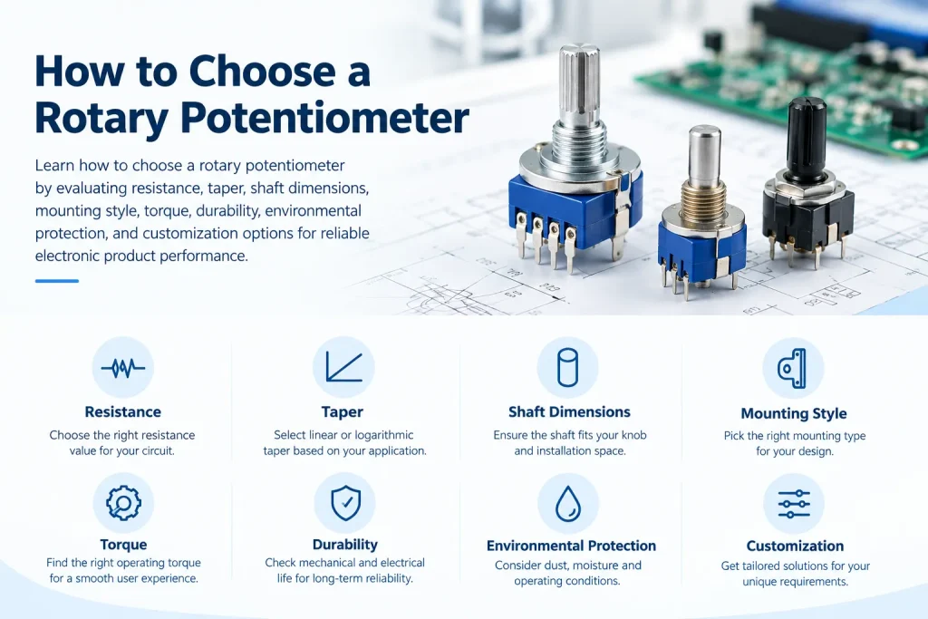
Rotary potentiometers remain an important choice for electronic products that require direct, continuous manual adjustment. From audio volume controls to industrial instruments and household appliances, the right component can improve operating feel, simplify circuit design, and support long-term product reliability.
For engineers and purchasing teams, selecting a rotary potentiometer involves more than matching resistance values. Shaft dimensions, resistance taper, mounting structure, operating torque, environmental protection, and production requirements all affect the final result. This guide explains the key factors to consider before choosing a component for a new design or replacement project.
1. What Is a Rotary Potentiometer?
A rotary potentiometer is an adjustable electrical component that changes resistance as its shaft rotates. Most conventional designs contain a resistive element and a movable contact called a wiper.
A three-terminal potentiometer can work as a voltage divider. By changing the wiper position, a circuit can obtain an adjustable output voltage. When only two terminals are used, the component can also function as a variable resistor in suitable circuit configurations.
Rotary designs are common because they provide a familiar control method and can be installed in relatively small spaces. Depending on their construction and electrical characteristics, they can be used in audio equipment, lighting controls, household appliances, industrial instruments, and other electronic products.
Before selecting a model, engineers should identify the exact function required. A component used for audio volume adjustment may have different taper and mechanical requirements from one used for calibration or industrial control.
2. Select the Correct Resistance Value
Resistance is one of the first specifications to confirm.
Common nominal values include 1kΩ, 5kΩ, 10kΩ, 50kΩ, and 100kΩ, although availability depends on the product series and manufacturer.
The correct value depends on the circuit design, including the input impedance of the following stage, the required current, and the expected output range. Choosing a value based only on what is commonly available may lead to unnecessary circuit changes.
For example, an audio circuit designed around a 10kΩ control should not automatically use a 100kΩ replacement. The different resistance can affect loading, signal response, and noise performance in some circuit configurations.
Before ordering, check the nominal resistance, allowable tolerance, and compatibility with the existing circuit. For replacement projects, confirm the original specification or measure the existing component when appropriate.
3. Understand Resistance Taper
Resistance taper describes how the resistance changes as the shaft moves.
Two common options are linear and logarithmic taper.
A linear-taper component changes resistance approximately in proportion to shaft movement. It is often suitable for adjustment tasks where a proportional electrical response is desirable.
A logarithmic, or audio-taper, component is designed to provide a nonlinear resistance change. This characteristic is useful in many audio volume controls because human hearing perceives loudness nonlinearly.
However, the best taper depends on the application and circuit design. A linear model is not automatically better for precision control, and an audio-taper model is not suitable for every sound-related application.
When replacing an existing component, verify the taper marking and terminal configuration. Using the wrong taper can make the control feel uneven or cause most of the useful adjustment to occur within a limited part of the shaft’s travel.
4. Choose the Right Shaft and Mounting Structure
Mechanical compatibility is a frequent source of problems during product development.
The shaft must fit the external knob, while the body and terminals must fit the enclosure and printed circuit board. Even a small dimensional difference can affect assembly.
Consider the following specifications:
- Shaft length: Determines how far the shaft extends beyond the panel or enclosure.
- Shaft diameter and shape: Must match the knob, coupling, or other mechanical interface.
- Shaft material: Metal and plastic designs offer different mechanical properties and cost considerations.
- Mounting style: Horizontal PCB mounting, vertical PCB mounting, and threaded-bushing designs suit different layouts.
- Terminal layout: Pin spacing and orientation must match the PCB footprint.
- Body dimensions: The component must fit within the available installation space.
Metal shafts may be appropriate where higher mechanical strength or a particular operating feel is required. Plastic shafts can be suitable for compact, lightweight, cost-sensitive designs.
Neither option is universally superior. The decision should reflect the intended operating environment, mechanical loads, assembly method, and product requirements.
For compact control panels, a small rotary potentiometer can help reduce installation space. Sunhorizon offers different rotary potentiometer structures, including compact models and dual-unit configurations.
Related product pages:
5. Compare Single-Unit and Dual-Unit Designs
The number of resistive sections is another important consideration.
A single-unit potentiometer contains one resistive channel. It is often sufficient for adjusting one signal or control parameter.
A dual-unit, also called a dual-gang potentiometer, combines two resistive channels operated by the same shaft. This arrangement is common in stereo audio equipment, where two signal channels need to be adjusted together.
However, a shared shaft does not guarantee identical electrical output from both sections. Engineers should check the required tracking performance, resistance tolerance, and taper characteristics when channel balance matters.
| Selection factor | Single-unit design | Dual-unit design |
|---|---|---|
| Resistive channels | One | Two |
| Typical application | Single-channel adjustment | Stereo or two-channel adjustment |
| PCB requirements | Usually simpler | Requires additional terminals and space |
| Main consideration | Resistance and taper | Channel matching and synchronization |
| Cost and assembly | Depends on model and volume | May reduce the need for separate controls |
For products requiring multiple synchronized controls, engineers should also evaluate whether a multi-gang design can meet the required mechanical and electrical specifications.
6. Check Operating Torque and Service Life
The user experience depends partly on operating torque, which describes the rotational force required to turn the shaft.
If the torque is too high, the control may feel stiff. If it is too low, it may feel loose or be easier to move unintentionally. The preferred range depends on the knob design, user expectations, and application.
Service life also deserves attention. Mechanical life and electrical life are related but distinct specifications.
Mechanical life concerns the number of operating cycles the mechanism can withstand under defined test conditions. Electrical life considers whether the component continues to meet specified electrical requirements after repeated operation.
Neither figure should be treated as a guarantee of service life under every real-world condition. Actual performance depends on operating frequency, environmental exposure, electrical loading, installation, and the manufacturer’s test method.
For products used frequently, ask the supplier for the applicable endurance specifications and test conditions rather than relying on a general claim such as “long life.”
7. Consider Dust, Moisture, and Operating Conditions
Environmental requirements should be established early in the design process.
Dust can interfere with moving contacts or affect operating smoothness, depending on the component construction. Moisture may create additional concerns for electrical insulation, corrosion, and long-term stability.
A sealed rotary potentiometer may be appropriate where the design requires improved protection against environmental contaminants. However, the word “sealed” does not automatically indicate a specific IP rating or suitability for immersion.
Confirm the protection level, test conditions, operating temperature range, and any relevant environmental requirements with the manufacturer.
For automotive, industrial, or outdoor applications, engineers should evaluate vibration, temperature variation, humidity, and mechanical stress as part of the complete product design.
8. When Should You Consider a Custom Potentiometer?
A standard component is often the most straightforward choice when its specifications match the design. Customization becomes worth considering when a standard model cannot meet important mechanical, electrical, or assembly requirements.
Possible customization items include:
- Shaft length, diameter, and shape
- Nominal resistance and resistance taper
- Horizontal or vertical mounting structure
- Terminal arrangement and PCB compatibility
- Operating torque and rotational characteristics
- Single-unit, dual-unit, or multi-gang configuration
- Packaging and production requirements
Before requesting a quotation, prepare a drawing or sample, the target resistance value, taper, dimensions, terminal layout, estimated order quantity, and intended operating environment.
A clear specification helps the manufacturer evaluate feasibility and reduces avoidable changes during sampling.
For OEM and ODM projects, it is also useful to discuss sample approval, production tolerances, inspection requirements, and how the approved design will be maintained during mass production.
9. What Should Buyers Confirm Before Ordering?
Purchasing teams should evaluate more than unit price.
A lower-priced component may not provide the best overall value if it requires PCB changes, additional assembly work, or repeated quality checks. Conversely, an expensive component may include features that the application does not need.
Before placing an order, confirm the following:
- The resistance value, tolerance, and taper match the circuit.
- The shaft and mounting dimensions match the mechanical design.
- The terminal layout is compatible with the PCB.
- Operating torque and life specifications suit the intended application.
- Environmental requirements are clearly defined.
- Sample testing and production inspection requirements are agreed upon.
- Lead time, minimum order quantity, and customization costs are understood.
Where a replacement is required, verify both electrical and mechanical compatibility. A component with the same nominal resistance may still differ in taper, rotation angle, pin arrangement, or shaft dimensions.
Conclusion
Choosing the right rotary potentiometer requires a balance between electrical performance, mechanical compatibility, environmental conditions, and purchasing requirements.
Engineers should begin with the circuit specifications, then verify resistance taper, shaft dimensions, mounting style, operating torque, and expected service life. Purchasing teams should confirm production consistency, inspection requirements, and customization feasibility before approving a supplier.
For projects with unusual space constraints or specific mechanical requirements, working directly with a manufacturer can help identify a suitable standard model or assess a customized design.
Sunhorizon, operated by Shenzhen Sanhezheng Electronics Co., Ltd., manufactures potentiometers, rotary encoders, and rotary switches, with customization options for different electronic control applications. Buyers can review the available product range or contact the company to discuss their project specifications.
Explore more:
For a technical inquiry, provide your drawing, target specifications, estimated quantity, and application requirements to help the team assess the most suitable solution.